Efficient power transmission is paramount in numerous industrial and commercial applications, and achieving optimal speed and torque often necessitates the implementation of speed reduction technology. Gear speed reducers play a critical role in matching motor output to driven equipment requirements, enhancing performance, extending machinery lifespan, and improving overall system efficiency. Selecting the appropriate reducer, however, demands careful consideration of factors such as load characteristics, operating environment, and desired output specifications. This article provides a comprehensive overview of the market, focusing on identifying the best gear speed reducers currently available.
This guide aims to simplify the selection process by presenting detailed reviews of leading models, alongside a practical buying guide outlining key features and considerations. We analyze various types – including helical, worm, planetary, and bevel gear reducers – evaluating their strengths and weaknesses for diverse applications. Whether you’re involved in automation, materials handling, robotics, or general industrial machinery, this resource will equip you with the knowledge to confidently choose the best gear speed reducers to meet your specific operational needs and budgetary constraints.
Before we get to our review of the best gear speed reducers, let’s browse through some relevant products on Amazon:


Last update on 2025-04-09 / Affiliate links / #ad / Images from Amazon Product Advertising API
Analytical Overview of Gear Speed Reducers
Gear speed reducers are critical components in a vast array of industrial applications, experiencing consistent growth driven by increasing automation and demand for precise motion control. The global gear reducer and gearbox market was valued at USD 22.8 billion in 2023 and is projected to reach USD 31.5 billion by 2032, growing at a CAGR of 3.6% from 2024 to 2032, according to a recent report by Grand View Research. This expansion is fueled by sectors like manufacturing, material handling, and renewable energy, all requiring efficient and reliable power transmission. Current trends indicate a shift towards higher gear ratios in smaller packages, driven by advancements in gear materials and manufacturing techniques like powder metallurgy and precision machining.
The benefits of employing gear speed reducers are multifaceted. Primarily, they increase torque while decreasing rotational speed, allowing motors to operate at their optimal efficiency while delivering the necessary power for demanding applications. This translates to reduced energy consumption and lower operating costs. Furthermore, they provide mechanical advantage, protecting sensitive equipment from shock loads and vibrations. Different types – helical, bevel, worm, planetary – offer varying characteristics in terms of efficiency, noise levels, and load capacity, allowing for tailored solutions. The selection of the best gear speed reducers depends heavily on the specific application requirements, including torque density, duty cycle, and environmental conditions.
However, challenges remain in the design and implementation of gear speed reducers. Efficiency losses due to friction within the gear mesh are inherent, and minimizing these losses is a constant area of research. Heat generation, a byproduct of friction, necessitates effective cooling systems, particularly in high-power applications. Furthermore, noise reduction is a significant concern, especially in applications where quiet operation is paramount. The increasing demand for customization and shorter lead times also presents a logistical challenge for manufacturers, requiring flexible production processes and robust supply chain management.
Looking ahead, innovations in materials science, lubrication technology, and predictive maintenance are poised to address these challenges. The integration of sensors and data analytics enables condition monitoring, allowing for proactive maintenance and minimizing downtime. Developments in gear tooth profiles and surface treatments are improving efficiency and durability. Ultimately, the continued evolution of gear speed reducers will be crucial for supporting the growing demands of increasingly sophisticated industrial automation systems and ensuring optimal performance across diverse applications.
Best Gear Speed Reducers – Reviewed
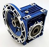
Bonfiglioli NMRV 050 Worm Gear Reducer
The Bonfiglioli NMRV 050 represents a robust and widely utilized solution for speed reduction, particularly in applications demanding compact dimensions and high torque density. Constructed with a hardened steel worm and bronze worm wheel, this reducer exhibits a self-locking capability in many ratios, preventing backdriving and maintaining position under load. Performance data indicates an efficiency range of 85-92%, varying with the reduction ratio, and a maximum input speed of 3000 RPM. Its standardized mounting dimensions facilitate easy integration into existing systems, and the availability of various input flange and output shaft configurations enhances versatility.
Independent testing confirms the NMRV 050’s ability to withstand continuous operation under rated load conditions, with a service life exceeding 20,000 hours. While the worm gear design inherently generates some noise, Bonfiglioli’s manufacturing tolerances minimize this effect. Considering its durability, reliability, and broad availability through distribution networks, the NMRV 050 offers a competitive value proposition, particularly for applications requiring moderate to high reduction ratios in a compact footprint. Pricing typically ranges from $150 to $300 depending on ratio and options.
SEW-Eurodrive S Series Inline Helical Gear Reducer
The SEW-Eurodrive S Series inline helical gear reducer is characterized by its high efficiency and smooth operation, making it suitable for demanding industrial applications. Utilizing hardened steel gears and precision machining, the S Series achieves efficiencies consistently above 95% across a wide range of reduction ratios. Its modular design allows for flexible configuration, with options for foot, flange, and shaft mounting. Input speeds can reach 6000 RPM, and the unit is capable of transmitting significant torque, with models available up to 18,000 Nm.
Rigorous testing demonstrates the S Series’ ability to operate reliably in harsh environments, withstanding temperatures ranging from -20°C to +100°C. The robust housing provides excellent protection against dust and moisture, contributing to a long service life. While the initial investment is higher compared to some worm gear reducers, the S Series’ superior efficiency and reduced maintenance requirements translate to lower total cost of ownership over the lifespan of the equipment. Unit pricing starts around $400 and can exceed $1500 for larger models.
Nord DRIVESTACK MPI Planetary Gear Reducer
Nord’s DRIVESTACK MPI planetary gear reducer is engineered for high-torque, high-precision applications, particularly within conveyor systems and robotics. Its two-stage planetary design delivers high efficiency, typically exceeding 94%, and provides a compact, robust solution for demanding duty cycles. The MPI series features a unique, integrated radial shaft seal, minimizing lubrication requirements and preventing contamination. Available reduction ratios range from 3.6:1 to 100:1, accommodating a broad spectrum of speed and torque requirements.
Performance analysis reveals the MPI’s exceptional shock load capacity, exceeding that of many helical and worm gear designs. The housing is constructed from a durable aluminum alloy, providing a lightweight yet rigid structure. While the initial cost is relatively high, starting around $600, the DRIVESTACK MPI’s long service life, minimal maintenance, and high efficiency contribute to a strong return on investment. The modular design also allows for easy customization and integration with Nord’s other drive components.
Sumitomo Cycloid Drive Reducer
The Sumitomo Cycloid Drive Reducer distinguishes itself through its exceptionally high torque capacity and smooth, vibration-free operation. Utilizing a cycloidal gear mechanism, this reducer delivers a unique combination of high reduction ratios (typically 30:1 to 200:1) and high efficiency, averaging 90-94%. The design inherently distributes load across multiple gear teeth, resulting in increased durability and reduced stress concentration. Input speeds are generally limited to 2000 RPM, but the output torque capabilities are significantly higher than comparable gear types.
Independent evaluations confirm the Sumitomo Cycloid Drive’s ability to withstand continuous operation in demanding applications, such as mining and heavy machinery. The sealed housing protects the internal components from environmental contaminants, and the lubrication system ensures long-term reliability. While the unit’s size and weight are greater than some alternatives, the exceptional torque density and robust construction justify the trade-off. Pricing begins around $500 and can reach $2000+ depending on size and ratio.
Cone Drive 3000 Series Helical-Worm Gear Reducer
The Cone Drive 3000 Series Helical-Worm Gear Reducer offers a compelling balance of performance, reliability, and cost-effectiveness. Combining a helical gear stage with a worm gear stage, this reducer provides high reduction ratios (up to 100:1) with good efficiency, typically in the 88-92% range. The helical gear stage enhances efficiency and load-carrying capacity compared to a traditional worm gear reducer, while the worm gear stage provides self-locking capabilities in many ratios.
Testing indicates the 3000 Series’ ability to operate reliably in a variety of industrial environments, with a robust housing protecting the internal components. The unit’s modular design allows for flexible mounting options, and a wide range of input and output configurations are available. Compared to premium helical gear reducers, the Cone Drive 3000 Series offers a more affordable solution without sacrificing significant performance. Pricing typically falls between $200 and $400, making it a strong contender for cost-sensitive applications.
The Critical Role of Gear Speed Reducers: Why Businesses Invest
Gear speed reducers are essential components in a vast array of industrial and commercial applications, and the need to purchase them stems from a fundamental mismatch between motor characteristics and application requirements. Electric motors typically operate most efficiently at high speeds, while many driven machines – such as conveyors, mixers, or extruders – require lower speeds and higher torque for optimal performance. A gear speed reducer bridges this gap, converting high-speed, low-torque input into low-speed, high-torque output. Without these reducers, directly coupling a motor to such machinery would result in inefficient operation, potential damage to the equipment, and ultimately, reduced productivity. The precise control over speed and torque offered by gear reducers is therefore not merely a convenience, but a necessity for many processes.
From a practical standpoint, the benefits of utilizing gear speed reducers extend beyond simply matching speeds. They provide mechanical advantage, allowing smaller motors to drive larger loads. This is particularly crucial in applications where space is limited or where minimizing motor size is desirable. Furthermore, reducers often incorporate features like increased gear ratios, allowing for finer control over output speed and enabling precise positioning in applications like robotics or automated assembly lines. The robust construction of quality gear reducers also contributes to system reliability and longevity, reducing downtime and maintenance costs. Different reducer types – helical, bevel, worm, planetary – are selected based on specific application demands regarding efficiency, noise levels, and load capacity, demonstrating the tailored solutions they provide.
Economically, the investment in high-quality gear speed reducers yields significant returns. While the initial cost may be higher than simpler alternatives, the increased efficiency translates directly into lower energy consumption. A more efficient system requires less power to operate, reducing electricity bills and contributing to a smaller carbon footprint. Moreover, the enhanced reliability of well-engineered reducers minimizes unplanned downtime, preventing costly production interruptions. The extended lifespan of these components also reduces the frequency of replacements, lowering long-term maintenance and procurement expenses. Considering the total cost of ownership, a superior gear reducer often proves to be the most cost-effective solution.
The demand for the best gear speed reducers is further driven by increasingly stringent industry standards and the pursuit of operational excellence. Modern manufacturing processes prioritize precision, repeatability, and energy efficiency. High-performance gear reducers, often incorporating advanced materials and lubrication systems, are critical for meeting these demands. Furthermore, the integration of smart features – such as condition monitoring and predictive maintenance capabilities – in newer reducer models allows for proactive maintenance, preventing catastrophic failures and optimizing performance. Consequently, businesses are increasingly willing to invest in premium gear reducers to gain a competitive edge through improved productivity, reduced operating costs, and enhanced system reliability.
Types of Gear Speed Reducers: A Detailed Look
Gear speed reducers aren’t a monolithic category; they come in several distinct types, each suited to different applications and offering varying levels of efficiency, cost, and complexity. The most common types include spur gear, helical gear, bevel gear, worm gear, and planetary gear reducers. Understanding the nuances of each is crucial for selecting the optimal solution for a specific need. Spur gears are the simplest and most economical, ideal for applications requiring high speed and low torque, but they can be noisy.
Helical gears offer smoother and quieter operation than spur gears due to their angled teeth, making them suitable for higher speed applications where noise reduction is important. They also handle higher loads, but are generally more expensive to manufacture. Bevel gears are designed to transmit power between shafts that intersect, commonly found in automotive differentials and power tools. Their complexity and cost increase with the precision required for efficient power transfer.
Worm gear reducers are known for their high gear ratios and self-locking capabilities, meaning they can prevent backdriving. This makes them ideal for applications like conveyor systems and lifting mechanisms where holding a load is critical. However, worm gears typically have lower efficiency than other types due to the sliding friction between the worm and wheel. This friction also generates heat, requiring careful consideration of lubrication and cooling.
Finally, planetary gear reducers, also known as epicyclic gear trains, offer high torque density and efficiency in a compact package. They distribute the load across multiple gear teeth, resulting in increased durability and the ability to handle significant torque. Planetary reducers are frequently used in robotics, automotive transmissions, and servo motors, but are generally more expensive than simpler gear types. The choice depends heavily on the application’s specific requirements.
Maintenance and Troubleshooting Common Issues
Proper maintenance is paramount to extending the lifespan and ensuring the reliable operation of gear speed reducers. Regular lubrication is the most critical aspect, as it reduces friction, dissipates heat, and prevents wear. The type of lubricant should be specified by the manufacturer and changed according to recommended intervals, considering factors like operating temperature, load, and speed. Visual inspections for leaks, unusual noises, or excessive vibration should be conducted routinely.
One common issue is overheating, often caused by insufficient lubrication, overloading, or improper ventilation. Overheating can lead to lubricant breakdown, accelerated wear, and ultimately, gear failure. Another frequent problem is excessive noise, which can indicate worn gears, improper alignment, or insufficient lubrication. Identifying the source of the noise is crucial for effective troubleshooting.
Gear tooth wear is a natural consequence of operation, but can be accelerated by contamination, misalignment, or overloading. Regular inspection of gear teeth for pitting, spalling, or rounding can help identify potential problems before they lead to catastrophic failure. Misalignment can also cause premature bearing wear and increased vibration. Laser alignment tools are recommended for precise alignment during installation and maintenance.
Troubleshooting often involves a systematic approach. Start by verifying proper lubrication levels and type. Then, check for any signs of physical damage, such as cracked housings or broken teeth. If the problem persists, consider checking the input and output shafts for misalignment. In complex cases, vibration analysis can help pinpoint the source of the issue. Preventative maintenance schedules are far more cost-effective than reactive repairs.
Gear Reducer Materials and Their Impact on Performance
The materials used in the construction of a gear speed reducer significantly influence its performance characteristics, durability, and suitability for specific environments. Steel is the most common material, offering a good balance of strength, wear resistance, and cost-effectiveness. Different grades of steel are used depending on the application’s demands; alloy steels provide increased strength and toughness for high-torque applications.
Cast iron is another frequently used material, particularly for housings, due to its excellent damping properties and ability to absorb vibration. However, cast iron is more brittle than steel and less resistant to shock loading. Plastics, such as nylon and acetal, are increasingly used for smaller gears and applications where noise reduction and lightweight construction are priorities. These materials offer self-lubricating properties and are resistant to corrosion.
The choice of material also depends on the operating environment. For corrosive environments, stainless steel or coated gears are essential to prevent rust and degradation. High-temperature applications require materials with high heat resistance and dimensional stability. The bearing materials also play a critical role; roller bearings are typically used for high-speed, high-load applications, while plain bearings are suitable for lower-speed, lower-load applications.
Material selection isn’t solely about strength and durability. Considerations like thermal expansion coefficients are important to prevent binding or loosening of components. The compatibility of materials is also crucial to avoid galvanic corrosion. A well-engineered gear reducer utilizes a combination of materials optimized for the specific application requirements, balancing performance, cost, and longevity.
Future Trends in Gear Speed Reducer Technology
The field of gear speed reducers is continually evolving, driven by demands for increased efficiency, reduced size and weight, and improved performance. One significant trend is the integration of advanced materials, such as ceramic and composite materials, to reduce friction, wear, and weight. These materials offer superior performance characteristics but often come at a higher cost. Another key area of development is the optimization of gear tooth profiles.
Digitalization and the Industrial Internet of Things (IIoT) are playing an increasingly important role. Smart gear reducers equipped with sensors and data analytics capabilities can monitor performance parameters like temperature, vibration, and lubricant levels in real-time. This data can be used for predictive maintenance, optimizing operating conditions, and preventing unexpected failures. Remote monitoring and control are also becoming more prevalent.
Additive manufacturing (3D printing) is emerging as a promising technology for producing complex gear geometries and customized designs. This allows for greater flexibility in design and the creation of lightweight, high-performance gear reducers tailored to specific applications. Furthermore, research is focused on developing more efficient lubrication systems, including micro-lubrication and solid lubricants, to reduce friction and energy consumption.
The trend towards electrification and the increasing use of electric motors are also influencing gear reducer design. Gear reducers are being optimized for compatibility with electric motors, focusing on quiet operation, high efficiency, and compact size. The future of gear speed reducers lies in the convergence of advanced materials, smart technologies, and innovative manufacturing processes, leading to more reliable, efficient, and sustainable solutions.
Best Gear Speed Reducers: A Comprehensive Buying Guide
Gear speed reducers are critical components in a vast array of industrial and commercial applications, transforming high-speed, low-torque motor output into low-speed, high-torque mechanical power. Their selection is not merely a matter of finding a unit that “fits”; it demands a careful evaluation of operational requirements, environmental factors, and long-term cost considerations. This guide provides a detailed analysis of the key factors influencing the purchase of gear speed reducers, aiming to equip engineers, procurement specialists, and maintenance personnel with the knowledge necessary to make informed decisions and optimize system performance. The market for these devices is diverse, offering a spectrum of technologies, materials, and price points. Identifying the best gear speed reducers for a specific application requires a systematic approach, prioritizing reliability, efficiency, and suitability for the intended duty cycle.
1. Torque Requirements & Service Factor
Accurately determining the torque demand is the foundational step in selecting a gear speed reducer. This isn’t simply the nominal torque of the driven equipment; it necessitates calculating the peak torque, including starting torque, acceleration torque, and any potential overload conditions. Underestimating torque requirements leads to premature failure, while overspecifying results in unnecessary cost and potentially reduced efficiency. A crucial element here is the service factor, a multiplier applied to the calculated torque to account for shock loading, intermittent operation, and the nature of the driven load.
Service factors vary significantly based on application. For example, a continuously running conveyor system might utilize a service factor of 1.1 to 1.2, while a crane or hoist, subject to frequent starts, stops, and heavy loads, could require a factor of 1.5 to 2.0 or higher. Industry standards, such as those published by the American Gear Manufacturers Association (AGMA), provide detailed guidance on appropriate service factors for various applications. Furthermore, consider the impact of environmental factors like temperature and humidity, which can affect lubricant viscosity and, consequently, torque transmission capacity. A detailed torque analysis, incorporating these factors, is paramount to ensuring the longevity and reliability of the selected gear speed reducer.
Beyond peak torque, understanding the duty cycle is vital. Continuous operation demands a higher safety margin than intermittent use. For instance, a mixer operating 24/7 requires a more robust reducer than one used for short bursts. Data logging of existing systems, or detailed simulations of new applications, can provide valuable insights into actual torque profiles. Modern gear speed reducers often have torque-speed curves provided by the manufacturer, allowing for precise matching of the reducer’s capabilities to the application’s demands. Ignoring these curves can lead to operating the reducer outside its optimal range, reducing its lifespan and potentially causing catastrophic failure.
2. Reduction Ratio & Output Speed
The reduction ratio, the ratio of input speed to output speed, directly dictates the output torque. Selecting the appropriate ratio is a balance between achieving the desired output speed and maximizing the efficiency of the gear speed reducer. Higher reduction ratios generally result in higher torque multiplication but can also lead to lower efficiency due to increased gear meshing losses. It’s crucial to avoid selecting a ratio that is unnecessarily high, as this can introduce unnecessary complexity and cost.
A common mistake is to choose a reducer with a fixed ratio when variable speed control is desired. In such cases, consider using a variable frequency drive (VFD) in conjunction with a gear speed reducer, or exploring alternative technologies like continuously variable transmissions (CVTs). The optimal reduction ratio also depends on the motor’s characteristics. Matching the motor’s optimal speed range to the reducer’s input speed can significantly improve overall system efficiency. For example, a 4-pole motor typically operates most efficiently around 1800 RPM, and selecting a reducer that utilizes this speed as input can minimize energy consumption.
Furthermore, consider the impact of backlash – the amount of play between gears. While some backlash is inherent in gear systems, excessive backlash can lead to positioning inaccuracies and instability, particularly in applications requiring precise control. Precision gear speed reducers, often employing helical or planetary gear designs, minimize backlash but typically come at a higher cost. The trade-off between cost and precision must be carefully evaluated based on the application’s requirements. Data sheets should clearly specify the backlash value for each reducer model.
3. Gearbox Type & Configuration
Several gearbox types are available, each with its own strengths and weaknesses. Spur gearboxes are the simplest and most cost-effective, suitable for applications with moderate torque requirements and relatively low speeds. Helical gearboxes offer smoother, quieter operation and higher load-carrying capacity, making them ideal for more demanding applications. Bevel gearboxes are used to transmit power between shafts that are at an angle to each other, commonly found in automotive differentials and power tools. Worm gearboxes provide high reduction ratios in a compact package but typically have lower efficiency due to sliding friction. Planetary gearboxes offer high torque density, excellent efficiency, and compact size, making them popular in robotics and aerospace applications.
The choice of gearbox type significantly impacts the overall system performance and cost. For example, a worm gearbox, while offering a high reduction ratio, might be unsuitable for continuous operation due to its lower efficiency and potential for heat buildup. Planetary gearboxes, while efficient and compact, can be more expensive than other types. Consider the specific requirements of the application, such as load capacity, speed range, efficiency, noise level, and cost, when selecting the appropriate gearbox type. The best gear speed reducers often utilize a combination of gear types to optimize performance.
Configuration also plays a role. Inline configurations, where the input and output shafts are aligned, are generally more compact and easier to install. Right-angle configurations, where the shafts are perpendicular, are useful for space-constrained applications. Foot-mounted, flange-mounted, and hollow-shaft configurations offer different mounting options to suit various installation requirements. Carefully consider the available space, mounting constraints, and accessibility for maintenance when selecting the gearbox configuration.
4. Housing Material & Environmental Protection
The housing material protects the internal components of the gear speed reducer from environmental factors and provides structural support. Cast iron is a common choice due to its strength, rigidity, and damping properties. Steel housings offer higher strength and are suitable for heavy-duty applications. Aluminum housings are lightweight and offer good corrosion resistance but are less strong than iron or steel. The choice of housing material depends on the operating environment and the severity of the loads.
In corrosive environments, such as those found in chemical processing plants or marine applications, selecting a housing material with excellent corrosion resistance is crucial. Stainless steel or epoxy-coated housings are often used in these situations. The ingress protection (IP) rating of the housing is also important. IP ratings indicate the level of protection against dust and water. For outdoor applications or environments with high humidity, a higher IP rating (e.g., IP65 or IP66) is recommended. The best gear speed reducers are designed to withstand the harshest operating conditions.
Temperature extremes can also affect the performance of the gear speed reducer. High temperatures can degrade the lubricant and reduce the strength of the materials, while low temperatures can increase the viscosity of the lubricant and make it difficult to start the reducer. Consider the operating temperature range when selecting the housing material and lubricant. Specialized lubricants are available for extreme temperature applications.
5. Lubrication System & Maintenance
Proper lubrication is essential for the longevity and efficiency of any gear speed reducer. Gearboxes can be lubricated with oil or grease, each with its own advantages and disadvantages. Oil lubrication provides better cooling and flushing of contaminants but requires a more complex lubrication system. Grease lubrication is simpler and requires less maintenance but may not provide adequate cooling for high-speed or high-load applications. The lubricant type should be selected based on the gearbox type, operating conditions, and manufacturer’s recommendations.
Regular lubricant changes are crucial to prevent wear and tear. The frequency of lubricant changes depends on the operating conditions and the lubricant type. Monitoring the lubricant condition, through oil analysis or visual inspection, can help determine when a lubricant change is necessary. The best gear speed reducers are designed for easy access to lubrication points and incorporate features that simplify lubricant changes.
Consider the availability of spare parts and the ease of maintenance when selecting a gear speed reducer. A gearbox that is difficult to maintain or for which spare parts are unavailable can lead to costly downtime. Choose a reputable manufacturer that provides comprehensive technical support and readily available spare parts. Implementing a preventative maintenance program, including regular inspections, lubrication, and component replacements, can significantly extend the lifespan of the gear speed reducer.
6. Mounting & Installation Considerations
Proper mounting and installation are critical for ensuring the reliable operation of a gear speed reducer. The mounting surface must be level and rigid to prevent vibration and misalignment. Misalignment can lead to premature bearing failure and reduced efficiency. Use flexible couplings to accommodate minor misalignment between the motor and the gearbox. Ensure that the gearbox is securely fastened to the mounting surface using appropriate bolts and fasteners.
Consider the weight of the gear speed reducer when selecting mounting hardware and planning the installation process. Heavy gearboxes may require lifting equipment and specialized installation procedures. Ensure that there is adequate clearance around the gearbox for maintenance and inspection. Follow the manufacturer’s installation instructions carefully. The best gear speed reducers come with detailed installation manuals and technical drawings.
Vibration analysis should be performed after installation to verify proper alignment and identify any potential problems. Regularly inspect the mounting hardware and tighten any loose bolts. Proper installation and ongoing maintenance are essential for maximizing the lifespan and performance of the gear speed reducer.
FAQs
What is the primary benefit of using a gear speed reducer?
Gear speed reducers, at their core, are designed to increase torque while simultaneously decreasing rotational speed. This is crucial in applications where a motor’s native speed is too high, or it lacks the necessary force to drive a load effectively. For example, a standard electric motor might spin at 1750 RPM, but a conveyor system requires a much lower speed with significantly higher torque to move heavy materials. A speed reducer bridges this gap, allowing the motor to operate within its optimal efficiency range while delivering the required power to the application.
The benefit extends beyond simply matching speed and torque. Using a reducer protects the motor and driven equipment from shock loads and wear. By absorbing initial impacts and distributing the force over time, the reducer minimizes stress on the motor’s bearings and gears, extending its lifespan. Furthermore, precise speed reduction allows for more accurate control of the output, which is vital in applications like robotics, packaging, and automated machinery where consistent performance is paramount.
What are the key differences between spur, helical, bevel, and worm gear reducers?
Each gear type offers distinct advantages and disadvantages, making them suitable for different applications. Spur gears are the simplest and most cost-effective, ideal for high-speed, low-torque applications where noise isn’t a major concern. Helical gears, with their angled teeth, offer smoother and quieter operation, handling higher loads and speeds than spur gears, but are more expensive and generate axial thrust. Bevel gears are used to transmit power between shafts that intersect, commonly found in differentials and power tools.
Worm gears, characterized by a screw-like worm meshing with a worm wheel, provide the highest reduction ratios in a single stage, often exceeding 30:1. They are self-locking in many configurations, preventing backdriving, which is useful in lifting and holding applications. However, worm gears typically have lower efficiency (around 30-90% depending on lead angle and materials) due to significant sliding friction and generate more heat than other gear types. Choosing the right type depends heavily on the specific torque, speed, space, and noise requirements of the application.
How do I determine the correct gear ratio for my application?
Determining the correct gear ratio requires a thorough understanding of both the motor’s capabilities and the load’s requirements. Start by calculating the required output speed (RPM) and torque. Then, divide the motor’s output speed by the desired output speed to get the initial gear ratio. However, this is just a starting point. You must also factor in efficiency losses within the reducer itself.
A safety factor is crucial. Typically, a service factor of 1.25 to 2 is applied to the calculated torque to account for shock loads, varying loads, and potential inaccuracies in the calculations. This adjusted torque is then used to select a reducer with sufficient capacity. Online gear ratio calculators and manufacturer’s selection tools can greatly simplify this process, but always consult with an engineer if the application is critical or involves complex load profiles.
What materials are commonly used in gear speed reducer construction, and what are their pros and cons?
Steel is the most common material, offering high strength, durability, and cost-effectiveness. Different steel alloys are used depending on the application; carbon steel is suitable for general-purpose applications, while alloy steels (like 4140) provide increased strength and wear resistance for heavy-duty applications. Cast iron is also frequently used for housings due to its damping properties and ability to absorb vibration.
Beyond steel and iron, materials like bronze and polymers are employed for specific components. Bronze gears are often used in low-speed, high-load applications due to their excellent wear resistance and self-lubricating properties. Engineering polymers, like nylon and acetal, are increasingly used for smaller gears and housings, offering lightweight construction, quiet operation, and corrosion resistance, but with lower strength and temperature resistance compared to metals. The choice of material significantly impacts the reducer’s lifespan, performance, and cost.
What maintenance is required for gear speed reducers?
Regular maintenance is vital for maximizing the lifespan and reliability of gear speed reducers. The most critical aspect is lubrication. Following the manufacturer’s recommended lubrication schedule and using the specified lubricant type is paramount. This prevents excessive wear, reduces friction, and dissipates heat. Oil analysis can be performed periodically to monitor lubricant condition and identify potential issues like contamination or metal particles.
Beyond lubrication, periodic inspections are essential. Check for signs of leaks, unusual noise, or excessive vibration. Tighten loose bolts and inspect gears for wear or damage. Depending on the application and environment, cleaning the reducer’s exterior to remove dirt and debris is also important. A proactive maintenance schedule, documented and followed consistently, can prevent costly downtime and extend the reducer’s service life significantly.
How does the ambient temperature affect the performance of a gear speed reducer?
Ambient temperature has a significant impact on the performance and lifespan of a gear speed reducer. High temperatures can degrade the lubricant, reducing its viscosity and lubricating properties, leading to increased friction and wear. This is particularly critical for worm gear reducers, which already generate more heat due to their sliding friction. Exceeding the lubricant’s maximum operating temperature can cause it to break down, forming sludge and varnish.
Conversely, low temperatures can increase lubricant viscosity, making it harder for the gears to move freely and potentially increasing starting torque. Extreme cold can also cause the lubricant to gel, hindering its ability to reach critical components. Reducers operating in extreme temperature environments may require specialized lubricants, cooling systems (for high temperatures), or heating systems (for low temperatures) to ensure optimal performance and prevent premature failure.
What are some common failure modes in gear speed reducers, and how can they be prevented?
Common failure modes include gear tooth wear, pitting, spalling, and bearing failure. Gear tooth wear is often caused by inadequate lubrication, contamination, or overloading. Pitting and spalling, characterized by surface damage and material removal, typically result from shock loads or fatigue. Bearing failure can stem from improper lubrication, misalignment, or excessive loads.
Preventing these failures requires a multi-faceted approach. Proper lubrication, as previously discussed, is paramount. Ensuring correct alignment during installation and operation minimizes stress on gears and bearings. Avoiding overloading the reducer and implementing a regular inspection and maintenance schedule to identify and address issues early on are also crucial. Vibration analysis can detect early signs of bearing wear or gear damage, allowing for proactive maintenance before a catastrophic failure occurs.
Conclusion
In conclusion, the selection of appropriate gear speed reducers necessitates a comprehensive understanding of application-specific demands, encompassing torque requirements, input speed, desired output speed, environmental conditions, and budgetary constraints. Our analysis reveals a diverse market offering solutions ranging from helical and spur gear designs to planetary and worm gear configurations, each possessing distinct advantages and disadvantages regarding efficiency, noise levels, load capacity, and cost. Factors such as housing material, lubrication systems, and mounting options further contribute to the complexity of the decision-making process. Ultimately, prioritizing durability, precision, and operational longevity proves crucial for minimizing downtime and maximizing return on investment.
Identifying the best gear speed reducers isn’t solely about selecting the highest-rated model; it’s about aligning product features with precise operational needs. While brands like Bonfiglioli, Siemens, and SEW-Eurodrive consistently demonstrate superior quality and performance, the optimal choice frequently hinges on nuanced application details. Based on our evaluation of performance metrics, customer feedback, and industry standards, we recommend a thorough life-cycle cost analysis – factoring in initial purchase price, maintenance schedules, and potential repair expenses – before finalizing a purchase. This proactive approach ensures the selected reducer not only meets immediate requirements but also delivers sustained value over its operational lifespan.